Reworking the 3D Printed Dropper Lever (V2)
- Jerry Wang

- Apr 19, 2020
- 5 min read
Updated: Mar 23, 2021
Failure Analysis
While the lever V1 lasted countless rides, it still eventually gave out. One of the reasons is that when the part was initially printed, it was only meant to be a prototype as a proof of concept, the part was printed with an incredibly low infill density. However, the lever has worked so well, that I eventually forgot the lever was a prototype and never changed it to a part that is printed with the final finish configuration.
The failure happened after 8 months of use during a ride. One problem with my dropper system is that the dropper post itself tends to seize up, thus taking a much harder push than normal to actuate. While trying to use the dropper lever on this ride, I gave the lever a hard push, and felt the lever gave out. Upon closer inspection, it looks like the cable stop that the cable housing rests on snapped, and it happened along the layer line. Looking at the cross section of the failure, I was reminded that the lever had a very low infill density, only meant for prototype, it was a wonder that cross-section area this small has lasted as long as it did.
With closer inspection, I actually noticed that the top clamp has many points of fracture through the translucency of the filament.
This means either the stress on the clamp is too great, causing it to fail internally over time, or the creeping effect of PLA has led to these micro-fractures. To remedy this, I plan to use a greater cross-sectional area for the top clamp to reduce stress, and perhaps try a filament material that is less affected by the creeping effect.
The rest of the parts held up fine, so the lever body that connects everything together is going to be the focus of this revision.
Other Improvements
One other problem with this design that arose was partly due to the material selection, partly design flaw. Over time, the bearing has loosened from its press fit with the body. The material I made the Lever V1 was PLA. PLA is known to loosen up the most after constant stress (an effect called creeping) out of all of the thermo-plastics for FDM. The press fit introduced constant stress, thus the part loosened up over time. During the 8 months of use, I could feel that the bearing would pop around in its cavity. With my new design, I needed a way to fully secure the bearing's inside the body that does not rely on friction only.
Back to the Drawing Board
Even before the failure of the Dropper V1, I had been looking for methods that better secure the bearing inside the body.
I had thought about using threads on 3d printed parts; the bearing would be secured by a large 3D printed lock ring that would thread onto the body. I rejected this idea because the repeated rotating motion would for sure work the lock ring itself loose during use. Adding some type of locking mechanism to the lock ring would only complicate things further.
I had thought of having the bearing slide into the body from the side, then secured by a tiny door or similar mechanism. Nope, still too complicated.
Another thought is that the bearing would be pressed into the cavity, and little clips on the size would stop it from falling out. I convinced myself not to pursue this path either. The tiny clips are a feature that is far too idealized for application of FDM. I also wanted serviceability in my lever design, and getting the bearing back out would surely break the clips.
All these solutions are doable via other means of manufacturing, but for FDM 3D printing, they are simply unfeasible.
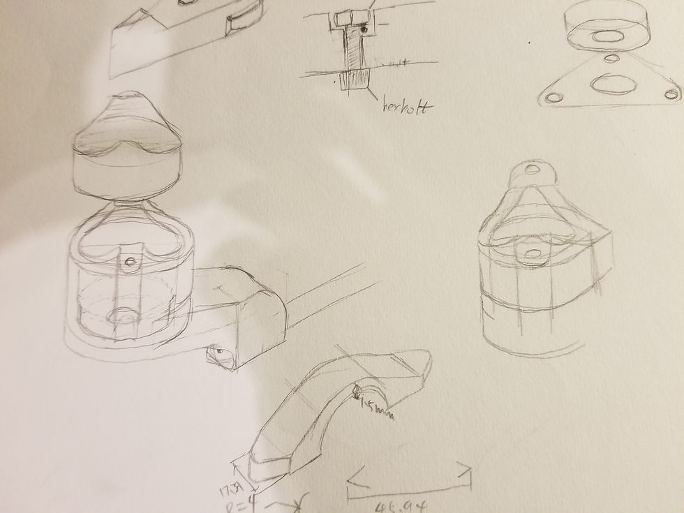
One final solution I came up with was simply having a plate that is secured by 3 screws sandwich the bearing between it and the body. This is a much more feasible solution compared to the previous ones. It is simple, and over-built. I am not a huge fan of this solution because it didn't feel elegant enough, it didn't align with the goal of this project when it started, which is a mostly 3D printed lever with a minimal amount of metal hardware required for assembly. This solution alone requires 6 M5 screws, which I am not even sure if I have laying around.

If I can't come up with better solutions, I was sure I am going with this one, because I needed my bike to work. And of course, a better one came up to me during a shower.
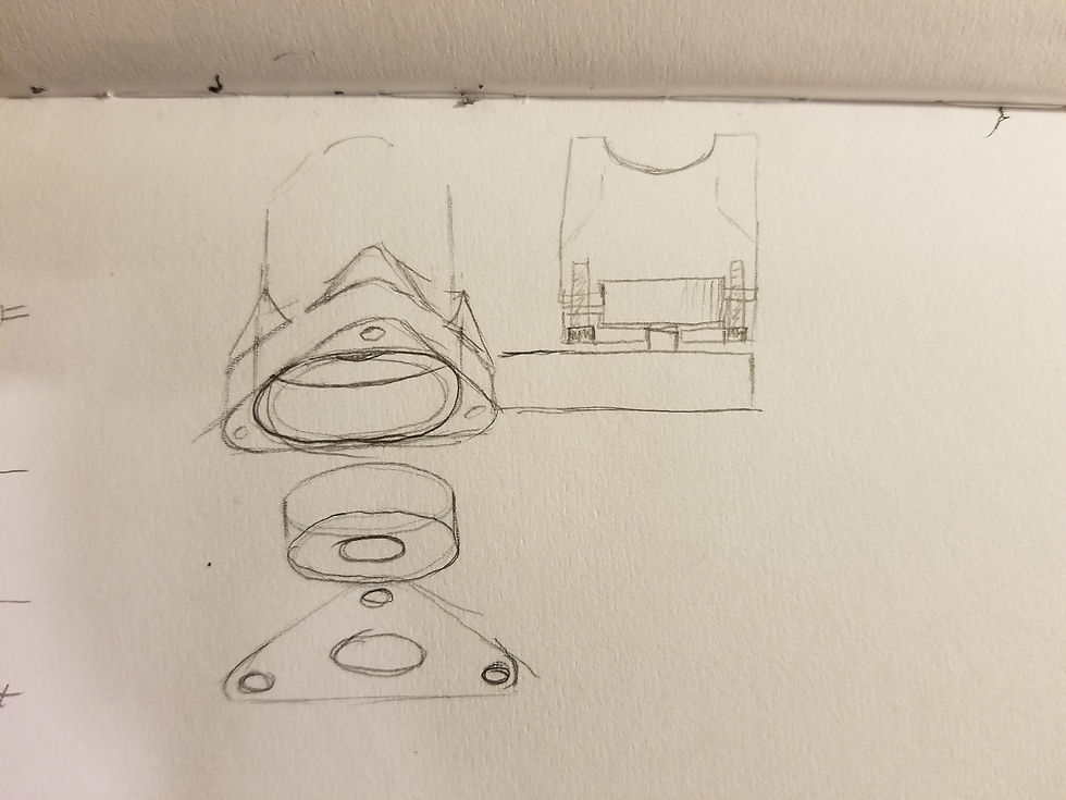
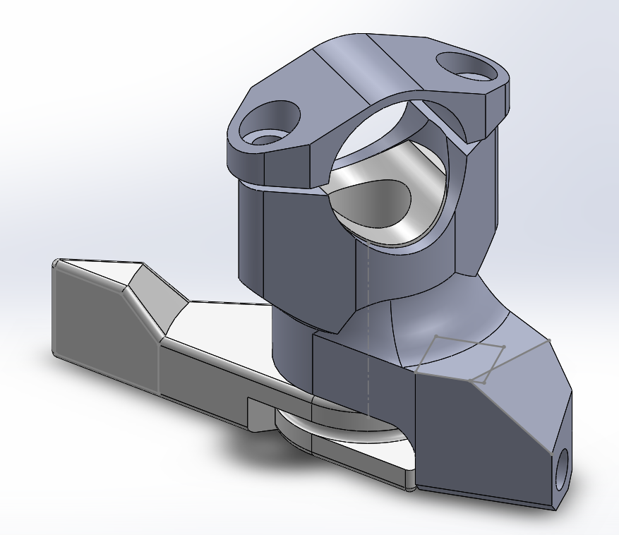
Instead of installing the bearing from the bottom, I would insert the bearing from the top side. The bottom of the bearing would sit on a lip, so there is no way the bearing could fall out. This however leaves the top side vulnerable, as the bearing would rock itself loose towards the top side, sucking the lever into the body and create problematic rotation clearance. This is where an additional part comes in. Since the top of the body is open, this would mean there is a cylindrical opening from the bearing to the handlebar. The bar would be clamped down against the body during the installation, so sandwiching something between the bearing's top and the handlebar could perfectly secure the bearing in every direction, preventing its movement and rotation along every axis. The sandwich block, the key to this design, would also be 3D printed, and it is shaped like a cylinder with a cylindrical cut out on top.

Another improvement aims to address the cable housing stop that failed. After taking the material properties course, I realized that the square extrusion for the cable housing stop has sharp angles, which can introduce regional stress, making the part fail much easier. The failure mode seemed to confirm this, as the failure happened along the layer line right at the transition to the square extrusion. To address this stress concentration, I simply added a fillet on the sharp angle, while not interfering with the function of other parts of this simple mechanism. In addition to that, I also elongated the length of the cable housing inserts into the body, enlarging the cross-sectional area of the cable housing holder, reducing the shear stress the layers experience.
After all these changes to address functional issues, I also change the profile of the lever as a cosmetic improvement. The lever now has more smoothed features, and overall has a better flow and is visibly beefier.

Printing Time
After the modeling stage, I exported the files and prepared them for printing. The parts came out great, but I was still using low-density infill, so it is still a prototype, because I don't have the material I wanted in my hands yet. The new materials I wanted were ABS and a modified PLA. ABS was chosen because of its great impact resistance, and its ability to stand up against creeping. The ABS part is intended to be used on the clamp, as it experiences high constant stress. One drawback of ABS is that it has less ultimate strength compared to PLA, therefore it needs to be designed thicker. On the other hand, I had a lot more expectation for the modified PLA, which boasts 8 times the impact strength than standard PLA, along with tensile strength on par with standard PLA.
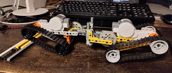
I printed the prototype V2 in standard white PLA again just as a proof of concept. I am not too eager to print this as a final version yet because I still have some features I wanted to add. Picture 2 shows the lever being used as a bearing press for itself; by putting another bearing between the clamp, I can actually press the bearing into position.
The lever prototype V2 was meant as a replacement to V1 to improve its design and get my bike working again. I still want to make changes to the lever design to make it more adjustable and compatible with a different cable routing setup. So look forward to at lease another update on the lever!


Comments