Custom Knob Wrench and a Dive into FEA/FEM
- Jerry Wang

- Jun 22, 2020
- 6 min read
Updated: Mar 23, 2021
The Need for a Custom Wrench
I have recently bought this bike rack, and the adjustment knobs on are quite difficult to turn. It looks like the previous owner has also struggled with these knobs, judging from all the marks on the plastic knobs from pliers and channel locks.

Therefore the idea of designing a custom wrench just for these knobs sparked in my head.
Introducing Topology Optimization
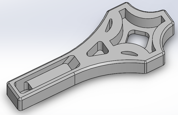
I quickly modeled something in Solidworks. I imagined the stress concentration near the knob would be quite high, so I added a lot of material near it, since I planned to 3d print the wrench with polymer. The design looked very beefy, and I thought it was probably a good design.

That was until I learned about topology optimization while browsing YouTube and came across a video made by Thomas Sanladerer. He demonstrated how he used Fusion 360 to turn a basic static support structure into an optimized shape. The finished result is a part that has the most rigidity for a given mass constraint, and the part has a very organic and bone-like look. I was hooked onto this idea of giving the program some constraints, and out-putting an optimized part, because it reduces the amount of guesswork when designing components, and the parts look really unique and aesthetically pleasing. Conventionally, this optimization process is used for cases where the performance to mass ratio is critical. This process benefits a lot from the popularization of additive manufacturing processes that has been taking place in the last decade, and has become more accessible due to the popularization of the technology.
Using Topology Optimization in Solidworks
After learning about this process, I was very pleased to find the 2019 version of Solidwork student edition does come with topology optimization. I am now wanting a complete redesign of the custom knob wrench (CKW) with topology optimization.
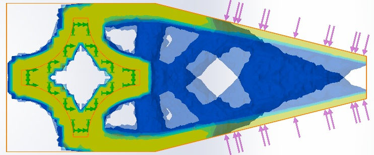
After looking at some tutorials on Solidwork's TopOp, I ran the very first analysis. I set up the constraints quite conservatively, a modest 45% weight reduction, with the constraint being finding the shape with the most rigidity. I set up the fixture to be at where the knob fits into the socket of the wrench, and the force to be applied is at the handle, simulating the turning of the wrench.

This wasn't quite the shape I expected. Turns out the material around the knob isn't needed much, it is very close to the preserved region constraint. In Thomas' case, He smoothed the model and printed the file directly. But as I learned in the Solidworks tutorial, most TopOp get redesigned in a parametric form by a human with the reference of the TopOped shape.

This is the CKW V2, result of my redesign of the CKW V1. Before I finalize the design, I wanted to see how much has my design with the help of TopOp improved the efficiency of the original design, so I ran a static stress analysis. I figured out the static analysis by myself, as it was very intuitive in Solidworks, and it is very similar to how I set up the TopOp.
After running a comparative simulation with the same input, it appears that CKW V2 has not improved the design, it did use 20% less material, and the stress appears to be in a smaller range, but the maximum Von Mises stress has actually increased. By applying the same amount of force, the CKW V2 is actually more likely to fail.
A Step Back
I started analyzing why this "optimization" did not work. After looking at the TopOp output and the FEA for both versions, I observed that the stress mainly concentrates around where the head of the wrench narrows into the handle. My interpretation of the TopOp also tells that the wrench needed more material near where the handle narrows. In the meantime, I thought changing the orientation of the knob socket from "+" to "x" would mean a narrower profile on the transition from the head to the handle, which should also help reduce the stress due to the shallower transition. This means another redesign.
This time I set up the piece that would be TopOped differently; the handle is wedged-shaped. Below is the result.
I was more aggressive on weight reduction, and more exciting shapes are appearing when I set the weight reduction to 70%. The result says that I need to keep the wedge-shaped handle for an efficient design. Even though the wedge-shaped handle isn't very conventional and doesn't seem very ergonomic (later it turns out to still be comfortable to hold), I believe it is still very usable, as long as one can wrap the hand around it. After some further thinking, I decided that the "x" configuration isn't the best way to do it, since the handle only attaches to two points on the wrench head, while the "+" attaches to 3 points. Therefore I ran the same TopOp for the wrench with the knob slot rotated back to the "+" configuration.
This produced a very asymmetrical design. I have considered keeping the asymmetry, the wrench would flip sides for tightening and loosening. However, the knob to be tightened actually has a tapered profile, if the wrench is to be usable on both sides, the tolerance would need to be looser, and the wrench could slip off the knob while tightening. In the end, I decided to settle for a single-sided, symmetrical design.
I mirrored the profile and super-imposed it on the original version to produce a symmetrical shape.

From this reference, I sketched up my interpretation of the symmetry:

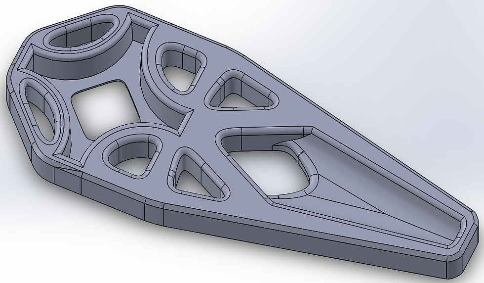
I then modeled the CKW V4 from the sketches and the mirrored image.

I added the thin ribs at the top of the wrench head because I realized the way I set up the simulation does not represent the real-world condition, the knob is made of a flexible polymer, therefore it should not have been treated as absolute fixed surfaces, because they are subject to deformation when a load is applied. The ribs therefore serve to spread the load more evenly on the knob, while also giving the wrench a more balanced look.
Performance Evaluation
At this point, I am quite happy with the design, but I still decided to evaluate the performance of the part to make sure all the effort I put in wasn't a waste. So I ran the same static analysis on the CKW V4 (0.5N at handle).

Below is the comparison chart between the versions, with V4 being the final version I settled for.

V4 is shown to have the lowest mass, the lowest maximum stress, and the lowest range of stress. Thus, this design is shown to have significantly improved efficiency for stress vs weight. With stress being lowered in the part, it would be able to withstand higher input force before reaching the Von Mises failure criteria and failing.
Material and Performance
ABS is chosen over the much easier to print PLA in this case for many reasons. ABS can withstand heat better, which means I would be able to leave the wrench in the car on a hot day. ABS is also a tougher material; despite having lower ultimate strength compared to PLA, print objects that are expected to stand up to abuse such as handtools would benefit more from ABS. Finally, ABS yields significantly before failing, while PLA fails by shattering due to its higher stiffness. If the tool does somehow fail during usage, PLA could potentially injure the user (myself), while I would be able to notice the deformation in the wrench made of ABS and stop using it.
I should also note that I am aware of the anisotropy in FDM printed parts, therefore the FEA I ran doesn't exactly apply the real printed wrench. FDM also has a semi-hollow infill, while the FEA assumes the part to be 100% isotropic and homogeneous. Despite all these discrepancies, I believe the simulation to still be useful because it helps to understand the general beam direction that produces parts with better performance. Therefore the discrepancies between the simulation and the manufactured part vis FDM is still yet to be determined.
Printing Process
After all the designs have been settled, it is time to finally print the wrench. The fit onto the nut is crucial, it has to fit just right. That's why I decided to print a few test-fit models to avoid wasting more plastic on the fit tuning.

It only took two tries to get the fit to my satisfaction. This was all done before I even began modeling the wrench, therefore the final version of the wrench was actually modeled from the test fit model.
This would be the largest ABS print I have done to date. I knew ABS suffered from a lot of print issues such as bed adhesion, warping, and delamination, and these become significantly more relevant on larger prints. All these issues were mainly caused by the higher print temperature, therefore the material shrinks more as it cools to room temperature, building up internal stress and causing the above issues. I used a passively heated enclosure to reduce the temperature difference the extruded plastic goes through, thus I was able to print with success on the first try.
Final Words
Overall, this was quite a rewarding experience working with computer-aided analysis during the design process for the first time. The printed part feels very solid during use, and I don't see how I would be able to break it.


Comments